Mitsubishi Q00-01H Serial (Gen1.3)
Review the following information for setting up and configuring the Mitsubishi Q00-01H Serial (Gen1.3) driver.
Manufacturing Connect Edge Compatible Series
Compatibility parameter | Compatible items |
|---|---|
Driver type | Serial |
Validated devices/series | MELSEC-Q |
To set up and configure this device in Manufacturing Connect Edge, you will need to do the following:
- Step 1: Set up and Configure the PLC Device
- Step 2: Set up the PLC Device in Manufacturing Connect Edge DeviceHub
- Step 3: Configure the List of Registers
Step 1: Set up and Configure the PLC Device
Record the serial communication parameters for the device. Otherwise, follow the steps below.
Refer to the following parameters.
Online simulator: YES
Extend address mode: NO
Broadcast command: NO
To configure your device:
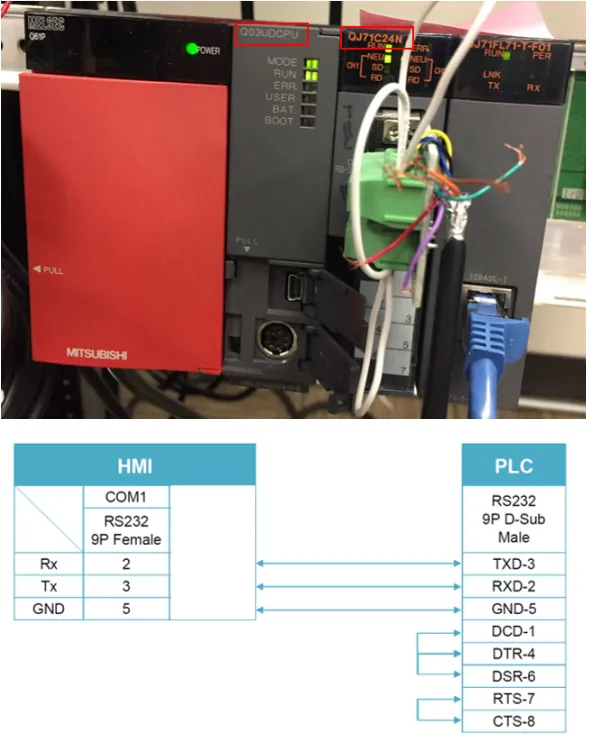
- Note down the following information and refer to it when needed. Device: Mitsubishi Q03UDCPU and QJ7124N Communication I/F: RS232. Refer to the following figure.
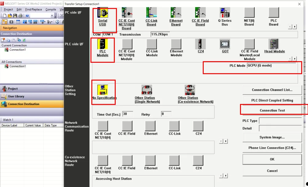
- Launch GX Works2 v1.560 software, and then click Online > Read from PLC.
- From the PLC Series Selection dialog box, select QCPU (Q Mode) from the PLC Series drop-down list, and then click OK.
- Set up communication parameters, and then click Connection Test.
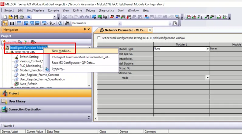
- Right-click Intelligent Function Module > New Module.
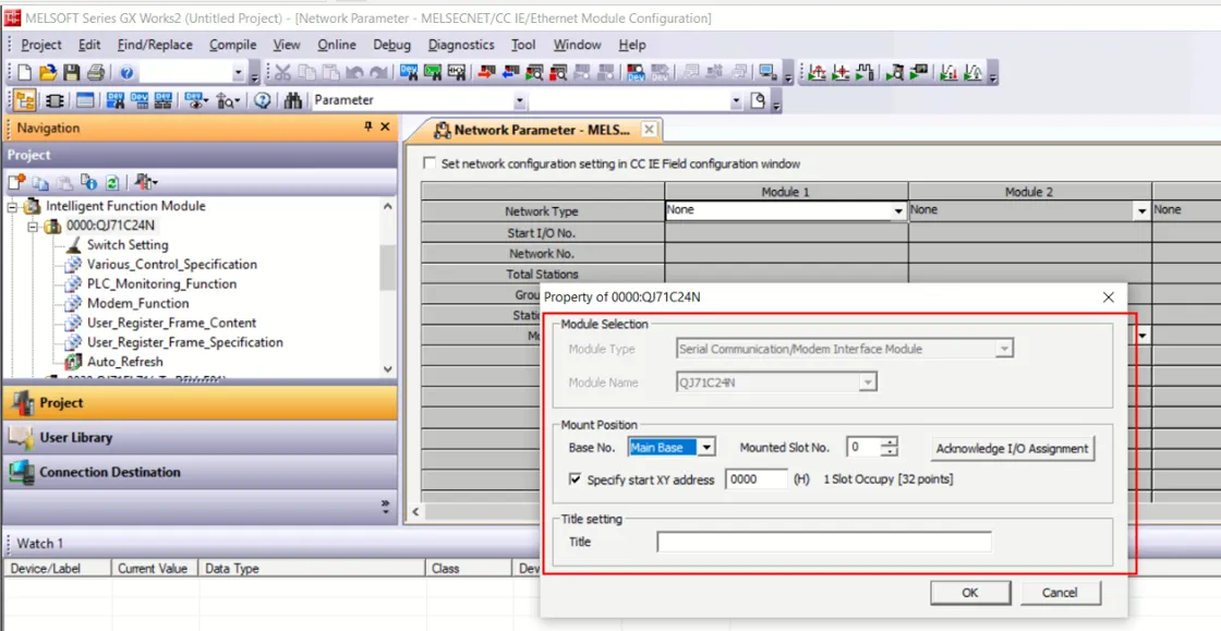
- Set up module parameters as shown below.
- Click Switch Setting and set up communication parameters as shown below.
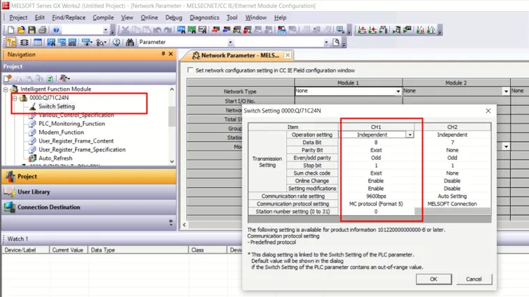
Step 2: Set up the PLC Device in Manufacturing Connect Edge DeviceHub
Configure the following parameters when you Connect a Device with this driver. Update default values to the specific set up of your device.
Parameter | Value |
|---|---|
Type | Mitsubishi |
Driver | Mitsubishi Q00-01H Serial (Gen1.3) |
Communication Port | Local Serial connection file path |
Data Bits | 8 |
Baud Rate | 9600 |
Parity | Even, Odd, None |
Stop Bits | 1 |
Step 3: Configure the List of Registers
When you Add Tags to the connected device, refer to the following register table and tag parameters.
Refer to the following additional resources:
Register Table
Name | Value Type | Address Format | Min Address | Max Address | Description |
|---|---|---|---|---|---|
X | bit | HHHH | 0 | 8191 | Input Relay |
Y | bit | HHHH | 0 | 8191 | Output Relay |
M | bit | DDDDD | 0 | 61439 | Internal Relay |
L | bit | DDDDD | 0 | 32237 | Latch Relay |
F | bit | DDDDD | 0 | 32237 | Annunciator |
V | bit | DDDDD | 0 | 32237 | Edge Relay |
B | bit | HHHH | 0 | 61439 | Link Relay |
TC | bit | DDDD | 0 | 2047 | Timer Coil |
SS | bit | DDDDD | 0 | 25471 | Retentive Timer Contact |
SC | bit | DDDDD | 0 | 25471 | Retentive Timer Coil |
CS | bit | DDDDD | 0 | 25471 | Counter Contact |
CC | bit | DDDDD | 0 | 25471 | Counter Coil |
SB | bit | HHH | 0 | 2047 | Special Link Relay |
S | bit | DDDD | 0 | 8191 | Step Relay |
DX | bit | HHHH | 0 | 8191 | Direct Input |
DY | bit | HHHH | 0 | 8191 | Direct Output |
TS | bit | DDDD | 0 | 2047 | Timer Contact |
SM | bit | DDDD | 0 | 2047 |
|
W | word | HHHH | 0 | 12187 | Link Register |
TN | word | DDDD | 0 | 2047 | Timer Current Value |
SN | word | DDDD | 0 | 2047 | Retentive Timer Current Value |
CN | word | DDDD | 0 | 1023 | Counter Current Value |
R | word | FFDDDDD | 0 | 32767 | File Register |
SW | word | HHHH | 0 | 2047 | Special Link Register |
Z | word | DD | 0 | 19 | Index Register |
ZR | word | HHHHH | 0 | 1042341 | File Register |
D | word | DDDDDDD | 0 | 4212735 | Data Register |
SD | word | DDDD | 0 | 2047 |
|
Tag Parameters
- Name: Select a register name from the drop-down list. The available options depend on the names in the register table.
- Value Type: Select a data type from the drop-down list. The available options depend on the register name selected.
- Polling Interval: Enter a value in seconds. This determines how often the tag should poll the register for data.
- Tag Name: Enter a name for the tag.
- Description (Optional): Enter a description for the tag.
- Address: Enter a tag address. The value must in the decimal format, within the allowed min/max range. Omit the leading zeros. The device might use the decimal (D), hexadecimal (H), or octal (O) address format. See the Register Table at the bottom of the dialog box. For Bit tags, append the bit address without the bit separator. The lowercase letters in the address format indicate how many digits you should enter in the Bit address.
- Tag Formula: Enter a formula for the tag to process the generated data. Two variables are permitted: value (current tag value) and timestamp (current tag UNIX time in milliseconds). The following math functions are available:
- sin
- cos
- sqrt
- tan
- power: power(x) performs the operation 10^x.
- log: log(x) is the natural logarithm (the logarithm is in base e).
- exp: exp(x) performs the operation e^x.
- Only Publish on Change of Value: Select the checkbox to only publish NATS messages when the value parameter changes to a new value. Change of Value only applies to boolean, numeric (such as int or float), and simple string data types. It does not apply to complex types, such as JSON or array. Poll-once topics will not be affected by Change of Value settings. These topics will still only see a single message.
- Meta Data: Metadata summarizes basic information about data. This feature allows you to define key-value pair data for the device output payload later on. Metadata can then be used to find, use, and reuse particular instances of data.
Note: If you use special characters in meta data key names, the special characters are replaced with underscore characters in the payload. This can cause two key names to be combined into one. For example, configuring the key names a**b and a&&b will cause only one key name to be created (a__b).